
Why, why, why are accelerometer datasheets so confusing? There's a reason. Accelerometer companies, understandably, try to position their products in the best light possible, and they often do so by using complicated terminology and units for the accelerometer's specifications.
I frequently talk with customers who don't fully understand the different specifications used on an accelerometer's datasheet. And this makes shopping for an accelerometer an even more difficult task than it already is!
In this post I will provide brief descriptions of 10 specifications often listed on accelerometer datasheets that you can use as a reference for whenever you are shopping around for accelerometers - the sensor that tells us how the world moves! I've also included a one page cheat sheet for quick reference - the link is at the bottom of the page.
Accelerometer Specifications
1. Accelerometer Type - Capacitive MEMS, Piezoelectric, or Piezoresisitve
There are three main types of accelerometers: capacitive MEMS, piezoelectric, and piezoresistive. The accelerometer's datasheet will, or should, tell you exactly what type it is because picking the right accelerometer type for your application can make all the difference. Generally a capacitive MEMS accelerometer is best for motion sensing applications (think human motion which is relatively slow/low frequency); piezoelectric is best for vibration; and piezoresistive is best for shock testing. Check out my blog post on accelerometer selection for a more in depth discussion and breakdown between the different types.
2. Frequency Response or Bandwidth
Bandwidth, or frequency response, is the most important parameter in accelerometer selection. You won't get accurate results if the bandwidth of the accelerometer doesn't include the frequency of the motion, vibration, or shock you are hoping to measure. The frequency response specification shows the maximum deviation of sensitivity over a frequency range.
The bandwidth is usually specified as a tolerance band, relative to the reference frequency sensitivity (usually 100 Hz). The tolerance band can be specified in percentage and/or dBs with typical bands being ±5%, ±10%, ±1 dB, and even ±3 dB. Most data sheets will have a typical frequency response curve to assist the user. The enDAQ sensor's (formerly Slam Stick) frequency response is shown below as an example (taken from the datasheet); it conveniently compares decibel to percentage deviation also.

Bandwidth information tells the user if the accelerometer can measure slow or static accelerations and also defines the upper frequency limit where the accelerometer will still be accurate. If the lower range of the bandwidth doesn't go to 0 Hz (called DC-response) the accelerometer won't be able to measure static accelerations like gravity or slow vibrations (< 2 Hz) like those seen in marine environments. DC-response accelerometers are also required for applications where velocity (by integrating the acceleration data), or displacement (double integrated) is of interest. Accelerometers that do not have a DC response will have an intrinsic decay function that will result in significant error during numeric integration, especially over long duration events. They can however be used to determine velocity or displacement amplitude of higher frequency (above 5 hertz) periodic motion, or simple harmonic motion (check out Mide's simple harmonic motion calculator for more information - Note: enDAQ is a division of Mide).
The frequency response of a sensor is typically governed at the high frequency end primarily by the mechanical resonance of the sensor. They are also the result sometimes of low-pass filtering used to prevent aliasing.
3. Sensitivity
Sensitivity of an accelerometer defines at what rate the sensor converts mechanical energy into an electric signal (the output); and this will define the acceleration measurement range of the accelerometer. Sensitivity is usually expressed as mV/g (millivolts or per g) or pC/g (picocoulombs per g), where g is the acceleration due to gravity or 9.81 m/s2; but digital output accelerometers will specify this as LSB/g (least significant bit per g). The sensitivity that you desire depends on the level of the signal you wish to measure. If you are interested in small vibrations then a higher sensitivity will be desirable to provide a cleaner signal (higher signal to noise ratio). When trying to measure higher amplitudes for shock events you will need a lower sensitivity. Piezoresistive accelerometers typically have a very low sensitivity (less than 1 mV/g) and require an additional amplifier.
4. Measurement Range
As its name implies this specification defines the range of acceleration amplitude the accelerometer can measure, directly proportional to the sensitivity. This is not to be confused with shock limits that define what acceleration level the accelerometer can tolerate before damage. I often find that customers underestimate the amplitude of the vibrations/accelerations they are looking to measure. It's generally good practice to only use the lower 20% of an accelerometer's measurement range to ensure ample margins for measuring unpredicted or unexpected accelerations.
5. Noise
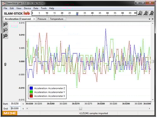 Noise levels can be defined in a number of different ways. Some accelerometers will define residual noise as a broadband RMS value, usually with the units of µV or µg. This is calculated by taking the root mean square of the signal without any mechanical excitation. Accelerations below the broadband noise level will not be resolvable. I've included an image to the right of the broadband noise of a ±25g an enDAQ sensor when sampling at 20 kHz with a 5 kHz low pass filter. The datasheet specifies a noise level as less than 0.01g RMS; and you can see that noise levels are generally within this ±0.01g range.
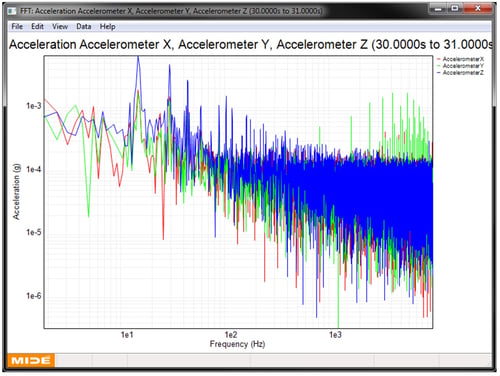 Some accelerometer datasheets provide a spectral noise parameter which will be specified as µV/√Hz or µg/√Hz. When this value is multiplied by the square root of the measurement bandwidth, this result is the nominal RMS acceleration noise of the sensor. Many accelerometers will specify this spectral noise density for different ranges because noise levels tend to drop at higher frequencies as shown in an FFT (Fast Fourier transform) of the noise levels of a sample sensor recording. This FFT was generated with the enDAQ Lab Software (formerly Slam Stick Lab).
6. Resolution
Resolution of an accelerometer is generally only given for digital output accelerometers or systems that incorporate an analog to digital converter. Resolution will typically be specified as bits which can then be used to calculate the resolution in acceleration units. For example let’s say that an accelerometer system has 16-bit resolution; this means that it has 216 (65,536) acceleration levels or bins it can measure. For a ±100g measurement range this equates to a resolution of 0.003g (200/65536) which is the smallest measurable acceleration level. In the broadband noise image, the data was generated with a ±25g accelerometer with 14-bit resolution (the resolution of the sensor goes as high as 16-bit for sample rates below 8.5 kHz). This also equates to a resolution of 0.003g (50/214); and you can see how these data points are always separated by at least 0.003g.
7. Filtering
Filtering can be integrated in some accelerometers to improve the signal quality. A high pass filter is inherent to all piezoelectric accelerometers (resistor and capacitor in series) which gives these accelerometers the AC response. A low pass filter is very common in accelerometers and accelerometer systems to prevent aliasing which can’t be filtered out in software. There are a number of different filter types (some common ones are Butterworth, Elliptical, and Bessel) that are explained in more detail in our post on different filters for vibration testing. Having some filtering for a digital accelerometer or accelerometer system is important though and products that do not have some filtering should be avoided.
8. Temperature sensitivity
Temperature sensitivity defines how the sensitivity of the accelerometer shifts with temperature. Accelerometers are mechanical systems so temperature will impact the device’s mechanical properties and thus the sensitivity of the accelerometer. Temperature sensitivity is typically defined as a percentage shift per degree Celsius (%/°C). For accelerometers that have a high temperature sensitivity (piezoelectric and piezoresistive tend to), you will need some form of temperature compensation to scale the output accordingly to offset the effect of temperature. Some accelerometers will include this compensation. If you will be testing in an environment that sees temperature changes and/or extremes, temperature sensitivity can’t be overlooked; it can lead to errors greater than 50%.
9. Transverse sensitivity
Transverse sensitivity defines how sensitive the accelerometer is to accelerations 90 degrees (or orthogonal) to the sensitive axis of the sensor. This parameter is expressed as a percentage. Ideally it should be 0% but due to manufacturing tolerances the transverse sensitivity is often 5% or 10%.
10. Triaxial
Triaxial indicates that the accelerometer can measure acceleration in all 3 directions. Most often you will prefer a 3-axis accelerometer to fully understand the response of your system in 3-dimensional space. Higher end accelerometers are typically only single axis which may require you to purchase and install three units for your testing which can be both expensive and time consuming.
Now What?
Before you can get to testing out your new skills, it's important to identify what you are looking to measure and select the right accelerometer type; this blog post on accelerometer selection provides some good information on this process. It also includes a few links to different accelerometer manufacturers.
If searching through the endless selection of accelerometers sounds a bit daunting, check out my blog on different vibration measurement products. Most of these systems incorporate an accelerometer which can make your test setup a little less complex to save you time and money.
Now that you understand the terminology used on accelerometer datasheets, you're ready to start shopping! Good luck, and don't hesitate to come back to this article and use it as a reference in your quest for the perfect accelerometer for your application!
If you'd like to learn a little more about various aspects in shock and vibration testing and analysis, download our free Shock & Vibration Testing Overview eBook. In there are some examples, background, and a ton of links to where you can learn more. And as always, don't hesitate to reach out to us if you have any questions!
For more on this topic, visit our dedicated Wireless Sensors resource page. There you’ll find more blog posts, case studies, webinars, software, and products focused on your wireless accelerometer testing and analysis needs.