It's time to reveal the mystery behind the accelerometer type you typically use in vibration and shock testing!
There are many different types of accelerometers, but piezoelectric accelerometers are the most popular for vibration and shock measurement.
In this post, I'll discuss how piezoelectric accelerometers work, the benefits and drawbacks of piezoelectric accelerometers over piezoresistive or capacitive MEMS, and finally, I'll provide links to where you can buy these sensors. Additional resources on vibration and shock measurement will also be provided.
How a Piezoelectric Accelerometer Works
The Piezoelectric Effect
Piezoelectric materials exhibit electro-elastic coupling... i.e. they convert a portion of the energy associated with any internal mechanical strain into recoverable electrical energy and vice versa. Basically, piezoelectric transducers convert mechanical energy (when strained) to an electric signal through the piezoelectric effect. This electric signal is proportional to the mechanical strain of the piezo and therefore, it is proportional to the vibration or shock event of the system.
Piezoelectric Accelerometer Configurations
The active element in a piezoelectric accelerometer is a piezoelectric ceramic. One side of the ceramic is rigidly connected to the accelerometer body, the other side has a seismic mass added. When the accelerometer is subjected to vibration, a force is generated which acts on the piezoelectric element and the seismic mass. Due to the piezoelectric effect, a charge output proportional to the applied force is generated from this vibration or shock. Over a wide frequency range the sensor mass and the sensor base have the same acceleration magnitude and therefore the sensor measures the acceleration of the accelerometer body.
There are 3 main sensor configurations: shear mode, compression, and bender.
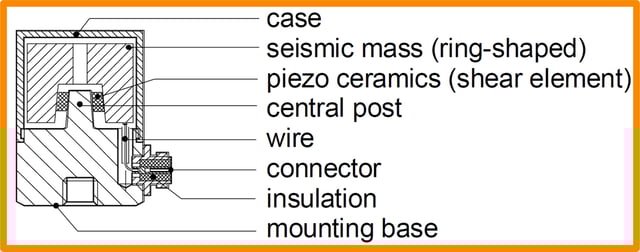
Shear Mode
The piezo wafers are configured to undergo shear deformation from acceleration (i.e. the piezo wafers are perpendicular to the base). This has become the most popular configuration because the piezo wafers are isolated from the base which helps reduce the temperature sensitivity and susceptibility to base strain. But this configuration typically has a relatively low sensitivity-to-mass ratio which means that you'll need a charge amplifier.
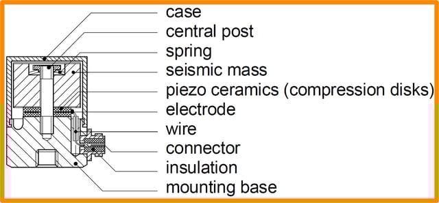
Compression Mode
With the piezo in compression, it is directly in line with the base and a seismic mass above. This provides a moderately high sensitivity-to-mass ratio but this results in effectively a spring-mass system between the piezoelectric element and the base. This can lead to easily produced erroneous results from base bending or thermal expansion. Therefore this configuration is rarely used except in high shock applications because of its robustness.
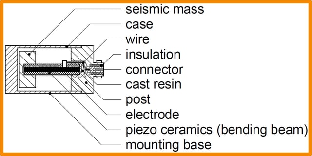
Piezoelectric Bender
The easiest-to-conceptualize configuration is with the piezoelectric element acting as a cantilevered beam with a tip mass. This produces the best sensitivity-to-mass ratio, so much so that this type of accelerometer will not require power (it can actually provide power - see energy harvesting). But this configuration also exhibits the highest temperature sensitivity, is relatively fragile (which is why laminated/packaged piezos can provide a benefit), and typically has a lower resonant frequency and therefore a lower bandwidth. So these are rarely used now for accurate testing, but they provide great benefit as an unpowered sensor to wake up the main sensing system.
Integrated Electronics Piezoelectric (IEPE)
Most piezoelectric accelerometers will have an integrated electronics circuit to convert the high impedance output (high voltage, low current) of the piezoelectric to a low impedance (low voltage, high current) voltage signal. These are commonplace now and most piezoelectric accelerometers will have the integrated electronics. The benefits include:
- Fixed sensitivity independent of cable length and quality
- Doesn't require expensive signal conditioners
- They are more expensive, but with less expensive cabling and electronics needs - the total system cost of an IEPE accelerometer based test setup is less
But there are applications where integrated electronics piezoelectric (IEPE) accelerometers are not ideal, and a charge mode output is preferred:
- Higher temperature application (IEPE are typically limited to 250°F)
- Doesn't require fixed excitation current (or any power supply)
- Offers the highest resolution, but special cabling is required to prevent noise
Note that IEPE and integrated circuit piezoelectric (ICP®) basically mean the same thing, although PCB Piezotronics technically has a trademark on ICP®. The terms IEPE and ICP have virtually become interchangeable within the industry. More information on PCB's ICP® accelerometers is available here.
Many of the major piezoelectric accelerometer suppliers out there have more detailed comparisons between charge mode and ICP/IEPE. Here are two good papers I came across on this topic:
How and Where to Use a Piezoelectric Accelerometer
Benefits of Piezoelectric Accelerometers
Piezoelectric accelerometers are by far the most popular in industrial testing applications. Capacitive MEMS accelerometers have become very popular in embedded electronics with their low cost and small size, but piezoelectric still reigns supreme with mechanical engineers performing shock and vibration tests. Here are some of their benefits:
- Low noise output
- Wide range - suitable for low amplitude vibration test as well as high amplitude shock
- Excellent linearity over their dynamic range
- Wide frequency range - they can be configured with a very high resonance
- Very popular so a wide variety of options are available to engineers to tune sensor selection to specific test application
Drawbacks of Piezoelectric Accelerometers
Although piezoelectric accelerometers are very popular for shock and vibration testing (for good reason) they do come with some drawbacks. Figure 4 provides the typical frequency response of a piezoelectric accelerometer. When using a piezoelectric accelerometer, you must be aware that piezoelectric accelerometers are great within their relatively wide frequency range, but at the outer limits they can experience very high deviations.

Low Frequency Roll-Off
Piezoelectric accelerometers are not capable of a true DC response. Piezos need dynamic forces to act upon it, a piezoelectric accelerometer can never directly measure the force exerted by gravity. The low-frequency rollover of the piezoelectric accelerometer is determined by the electronic circuit and can be tuned so that you can measure very low-frequency (< 1 Hz) vibrations like those in seismic or large structure applications. But they will never be able to measure static acceleration levels - do not expect a 1g offset from a piezoelectric accelerometer due to gravity!
For many applications, the low frequency vibrations and gravity vector are of little interest, and it can actually be helpful to have the accelerometer effectively act as a high pass filter.
Amplification at Resonance
At resonance, significant amplification occurs. Typically, at about 1/5 the mounted resonant frequency the accelerometer is a positive 5% deviation from the actual vibration level. At about 1/3 the resonant frequency, the accelerometer is at a positive 10% deviation. At about 1/2 the resonance, the deviation has grown to 3 dB (positive 41%). At resonance, the amplification is typically 30 dB (over 30x).
The amplification that occurs at or near resonance is significant and must be avoided, or at least identified. When I used to offer support to customers of our enDAQ sensors (formerly known as Slam Stick vibration data loggers) that have an embedded triaxial piezoelectric accelerometer, I found myself frequently fielding questions that could be answered with the plot shown in Figure 4. Picture the following scenario:
You may have a test where the true acceleration level is 10g and you are using a 100g accelerometer - you have plenty of clearance to prevent clipping! But... if this 10g acceleration level is at or near the resonant frequency of your accelerometer - watch out! That thing will be experiencing and reporting an acceleration of 300g. Its resonant frequency (or the resonance of the mounting you used) amplified the acceleration levels to such a degree that it made the accelerometer useless.
Amplification due to resonance can not be prevented or filtered out electronically - it's purely a result of the mechanical structure inside the accelerometer and/or the coupling between it and your test fixture - i.e. mounting matters too! The only way to prevent this amplification is to a) avoid using an accelerometer with a resonance within the frequency range of your test environment or b) mechanically filter the frequency through the use of double sided tape, duct seal putty, or even vibration isolators. Some accelerometers will also be available with internal damping to reduce this amplification at resonance - but this typically reduces the bandwidth of the accelerometer.
Saturation of the Charge Amplifier
Another drawback of the amplification that occurs at high frequencies and resonance, is that the amplification can cause the accelerometer to experience a shock amplitude that exceeds its measurement range. When the input acceleration levels (including those amplified by mechanical resonance) exceed the sensor's measurement range - this will saturate the internal charge amplifier.
Figure 5 provides a few plots from testing one of our engineers did on an AR15 rifle with two enDAQ sensors: one with a piezoresistive accelerometer and the other with a piezoelectric accelerometer. The data from the piezoresistive accelerometer indicated that the shock levels should be "only" around 500g. The piezoelectric had a ±6,000g measurement range, should be plenty wide enough to capture the event. But the vibration from the gun shot had significant high-frequency content in it that excited the piezoelectric accelerometer's resonance. This caused the output of the accelerometer to saturate its internal charge amplifier which results in an exponential decay that lasted about one second.
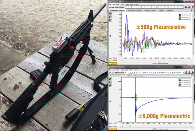
Engineers typically see this type of data and immediately assume that there is something wrong with their sensor and/or the electronics. But that's not the case, the high-frequency content in the test simply excited a resonance in your sensor and/or the mounting. This exponential decay is the key indicator of amplifier saturation. Either mechanical damping is needed, or a different sensor type or measurement range.
PCB Piezotronics has a great white paper with more information on this exponential decay that occurs from charge amplifier saturation.
Where to Buy Piezoelectric Accelerometers
Piezoelectric accelerometers are very popular, therefore they are available in a variety of measurement ranges and from a variety of vendors. I broke out the list of vendors by whether or not they support e-commerce (buy online).
E- Commerce
I hate when I need to "request a quote" to find out pricing or to buy something I need/want. I understand the value of the "request a quote" process for large orders to establish that relationship with the potential customer, but when you just need a couple accelerometers for a test - you just want to buy it without speaking to anyone! The following two companies have an e-commerce platform to allow you to directly purchase most of their accelerometers right online.
Request a Quote
These next four companies all have an extensive sensor suite and make good products, but you'll need to speak with a sales rep to get pricing and to order your accelerometers.
Accelerometer Data Loggers
Another option that is often overlooked is to buy an all-in-one system that incorporates the accelerometer(s), electronics, and power source all in one package. This can be very useful for:
- Initial testing to help you identify which accelerometer type/measurement range you need and where to mount them
- Testing in the field or away from the lab where it can be difficult to transport and set up all the accompanying equipment (DAQ, power, signal conditioners, and wiring)
- Quick tests where you need data quickly to get an idea of your test environment
- Engineers with limited experience in shock and vibration testing - some of the electronics set up can be quite daunting and time-consuming
- Limited budget - most piezoelectric accelerometers will typically cost $1,000 per channel, not to mention the cost for the accompanying electronics
- Long duration testing - set it and forget it
Data loggers will not typically be used for modal testing though or any application where very accurate synchronization (including phase information) is required between sensors.
Check out our blog that rates the top 11 vibration data loggers. This lists a few different options out there, including enDAQ's sensors (formerly Midé’s vibration data loggers (full disclosure - I work at Midé) that incorporate a few accelerometer types into a simple, easy-to-use accelerometer logger to meet a host of different motion, vibration, and shock measurement applications.
Additional Resources
For more exhaustive papers/discussions on piezoelectric accelerometers, refer to these two papers:
- Piezoelectric Accelerometers: Theory and Application
- Piezoelectric Accelerometers and Vibration Preamplifiers
For an overview of different accelerometer types, check out our blog on accelerometer selection. This details the pros and cons of piezoelectric, piezoresistive, and capacitive MEMS accelerometers for different applications.
If you'd like to learn a little more about various aspects of shock and vibration testing and analysis, download our free Shock & Vibration Testing Overview eBook. In there are some examples, background, and a ton of links to where you can learn more. And as always, don't hesitate to reach out to us if you have any questions!
For more on this topic, visit our dedicated Wireless Sensors resource page. There you’ll find more blog posts, case studies, webinars, software, and products focused on your wireless accelerometer testing and analysis needs.