Thermodynamic Theory of the Ideal Stirling Engine
 Stirling engines are one of those devices that have fascinated many engineers (including myself) over the years, especially when we’re young and impressionable, before we’ve gotten too cynical about the world. It’s also one of those technologies that hasn’t really been widely adopted, despite YouTubers cries of "free energy," so it obviously isn’t the perfect solution for many problems, but for certain applications they really are neat engines.
The Midé team has been recently putting in long hours to get a new Stirling project up and running for the US Marines. I chose the Stirling cycle engine for this application because of its naturally high efficiency and because it's an external combustion engine. To support this project I had a significant amount of research to do on the theory that govern Stirling engines – so that we could better design a solution for our military. In this post I’ll share with you some of the basics I learned and provide a tool to help visualize the Stirling cycle. Hopefully this tool will help you double check some of the basic calculations you might like to do, as well as provide a handy way of plotting some of the properties for an ideal Stirling cycle. You can find the calculator on this page: Ideal Stirling Cycle Calculator

Figure 1: An early Stirling engine prototype made at Midé as part of a project for the Marine Corps.
Overview
A Stirling engine is a specific flavor of heat engine formulated by Robert Stirling in 1816; this means it can transform the flow of heat into mechanical work (such as spinning a crankshaft). The key term is “flow of heat”; there must be two “reservoirs” that are separated, and these reservoirs must be at different temperatures in order for this flow to take place between them. If you put a thermal conductor between the two reservoirs over time they would both approach the same temperature, indicating that energy is “flowing” from the hot reservoir to the cold reservoir.
The Stirling engine harnesses this flow of energy from hot to cold and siphons some of it off as mechanical work. The Stirling engine needs a hot section and a cold section that are insulated from each other, the clever way a working fluid is routed between the two sections allows the engine to produce mechanical work. Heat is transferred from the hot section to the engine, some of the energy leaves the engine as useful mechanical work, and some of it leaves as heat transfer to the cold section. Remember that energy can never be destroyed so if you add up all the energy leaving the engine (i.e. useful work + heat transfer into the cold section) it must equal the amount of energy entering the engine as heat transfer from the hot section. This energy balance is the first law of thermodynamics and always holds.

Figure 2: Heat engine thermodynamic diagram

Equation 1: First law of thermodynamics for a Stirling engine, the first law is simply an energy balance of the system
Comments on Thermal Efficiency
The ratio of useful work to the heat transfer into the engine is called thermal efficiency. Think of it as the ratio of what you want (useful mechanical work) divided by what costs (heat transfer into the engine).

Equation 2: Calculating thermal efficiency for a Stirling
Efficiency can never be higher than 1. An efficiency of 1 would mean that all the heat transfer into the engine becomes useful work and there is no heat transfer to the cold section at all. An efficiency of 0 indicates that no useful work is produced and that all heat transfer from the hot section simply leaves the engine as heat transfer to the cold section. If you put two bricks next to each other, one hot and one cold, inside a perfectly insulated box and left them there for a while you would come back to find two warm bricks. This is technically a heat engine with an efficiency of 0; heat was transferred from the hot brick to the cold brick with a 1:1 ratio, producing no useful work in the process.
It turns out that efficiency can’t ever equal 1 either; sorry about that, the second law of thermodynamics is a real creep. Deriving the relation that bounds physically possible efficiency levels is a whole other topic, but it’s called the Carnot efficiency, named after Nicolas Léonard Sadi Carnot. He was able to postulate the maximum efficiency one could expect without violating the second law of thermodynamics. One can calculate the Carnot efficiency knowing only the temperatures of the hot section and the cold section between which a given heat engine is working. This means you’ll never have a heat engine that doesn’t reject at least some heat to the cold section.
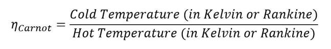
Equation 3: Carnot efficiency limits realistic engine performance

Figure 3: Example Carnot or Stirling thermal efficiency vs. hot section temperature
When one plots out the possible Carnot efficiency given the hot section temperature it can be seen that the larger the temperature difference between the hot side and the cold side the higher the possible efficiency. Not all engines can even theoretically (not to mention realistically) achieve Carnot efficiency. For example, the perfect diesel engine could never, even in a perfect world, match the efficiency of the theoretical Carnot heat engine. Certain other types of heat engines can match the Carnot engine in theoretical performance. The Stirling engine is one example of this. Therefore, the Carnot efficiency at a given hot section and cold section temperature is equal to the Stirling efficiency between the same hot and cold sections.

Equation 4: Ideal Stirling thermal efficiency is equal to the Carnot efficiency
To have a Stirling run continuously you need to have a hot section that gets constantly heated by some source, and a cold section that is cooled in some way. Without constantly heating the hot section and cooling the cold section eventually enough heat would be transferred between the two that you would just end up with two warm sections. Once this happens you no longer have this temperature differential between sections, efficiency would drop to 0, and no heat would be transferred through the engine since no temperature differential exists.
For Midé’s engine, the hot section is heated by burning biomass materials, and the cold section is cooled by water that then runs through a radiator. This allows us to keep the hot section at about 900 K and the cold section at about boiling water temperature (373 K). If you do the math to calculate the Carnot efficiency (and therefore the Stirling efficiency) these temperatures mean that one could never expect to get more than an efficiency of 0.58 without the universe imploding. Unfortunately, right away almost half the energy you put into our engine is GUARANTEED to come out as waste heat transfer to the cold section. Right now we’re just talking about absolutely perfect engines, and that’s all which will be discussed in this post, but in the real world there are all kinds of other factors that make it impossible to reach the Carnot efficiency level. You’re a superstar if you can get half of Carnot.
The Stirling Engine as a Cycle
Heat engines are cyclic, and that’s the case for the Stirling engine. In the case of a reciprocating engine, like what we've built, a process occurs between the hold section and the cold section, which repeats at a certain frequency. Heat is absorbed into the engine in pulses and then rejected to the cold section and as work in pulses. Usually a flywheel is added to the engine to smooth out these pulses and keep the mechanism turning. The heat from the hot section is transferred to the cold section via some type of working fluid (air, helium, hydrogen, nitrogen, or any other type of gas, some are better than others). For a Stirling it’s possible to describe the thermodynamic cycle in four sections.

Figure 4: The ideal Stirling cycle
State 1 to 2
At state 1 the working fluid is at a maximum volume, minimum temperature, and minimum pressure. From state 1 to state 2 the power piston compresses the working fluid while heat is transferred out of the system which keeps the working fluid at a constant low temperature. When the engine is in state 2 the working fluid is in a compressed state (high pressure and low volume), but remains at the same temperature as state 1. The work that was required to compress the volume is provided by stored energy in the engine’s flywheel.
State 2 to 3
At state 2 the working fluid is at a minimum volume, minimum temperature, and medium pressure. Between states 2 and state 3 the volume is held constant while heat is added by the hot section to increase temperature.
State 3 to 4
At state 3 the working fluid has achieved a maximum temperature, maximum pressure, while also at a minimum volume. From state 3 to 4 the working fluid is allowed to expand, doing useful work while it does so. During the expansion process more heat is added to keep the system at a constant temperature. The energy provided during this expansion outweighs the energy that was required to compress the volume between states 1 and 2, providing a net positive work out.
State 4 to 1
To return the engine to the state 1 where it began heat is removed from the working fluid while volume is kept constant.

Figure 5: A loop showing the relation between pressure and volume during a cycle of the Stirling engine, and with each state labelled
Summary of Equations
It’s possible to calculate the fluid properties at all these different states with the following formulas:

Additionally, useful work produced can be calculated with the following formula. CR stands for “Compression Ratio” (max engine volume divided by min engine volume). Please note that this formula gives the amount of work per unit mass of working fluid per revolution of the Stirling engine. Temperatures must also be in an absolute scale (i.e. Rankine or Kelvin).

Equation 5: Work per unit mass of working fluid delivered by an Ideal Stirling engine per revolution (cycle)
It’s important to keep in mind that all these numbers presented are for the ideal Stirling cycle, which will never exist in real life, all real engines are approximations of the ideal thermodynamic cycles. Knowing how to modify these ideal relations to reflect the real world is a whole other topic, one that might be treated in a future article!
Real Stirling Configurations
In order to control when heat is transferred to or from the working fluid most Stirling engines have what is called a “displacer” piston which simply prevents contact between the working fluid and either the hot section or the cold section depending on its position. To change volume of the system there is usually some type of power piston which reciprocates in a cylinder bore, often this piston is connected to a crankshaft in order to collect the useful work.
There are many ways in which an engineer might choose to mechanically link the power piston, displacer piston, and heat exchangers in order to produce the effects needed during a Stirling cycle. No mechanism perfectly mimics the motions needed, therefore in real Stirling engines one source of loss is the “approximation” of the cycle which is necessary to build a real machine. Two of the most common types of engine configurations are the beta type and the alpha type. The Midé Stirling engine is the beta type.

Figure 6: A real Stirling engine, alpha configuration (Animation Source: https://commons.wikimedia.org/wiki/File%3AAlpha_Stirling.gif)
 Figure 7: A real Stirling engine, beta configuration (Animation Source: https://commons.wikimedia.org/wiki/File%3AStirling_Animation.gif)