How Electronic Components Work
Electronic gadgets have become an integral part of our lives. They have made our lives more comfortable and convenient. From aviation to medical and healthcare industries, electronic gadgets have a wide range of applications in the modern world. In fact, the electronics revolution and the computer revolution go hand in hand.
Most gadgets have tiny electronic circuits that can control machines and process information. Simply put, electronic circuits are the lifelines of various electrical appliances. This guide explains in detail about common electronic components used in electronic circuits and how they work.
In this article I will provide an overview on electronic circuits. Then I will provide more information on 7 different types of components. For each type I'll discuss the composition, how it works, and the function & significance of the component.
Electronic Circuit Overview
An electronic circuit is a structure that directs and controls electric current to perform various functions including signal amplification, computation, and data transfer. It comprises several different components such as resistors, transistors, capacitors, inductors, and diodes. Conductive wires or traces are used to connect the components to each other. However, a circuit is complete only if it starts and ends at the same point, forming a loop.
The Elements of an Electronic Circuit
The complexity and the number of components in an electronic circuit may change depending on its application. However, the simplest circuit consists of three elements, including a conducting path, a voltage source, and a load.
Element 1: Conducting Path
The electric current flows through the conducting path. Though copper wires are used in simple circuits, they are rapidly being replaced by conductive traces. Conductive traces are nothing but copper sheets laminated onto a non-conductive substrate. They are often used in small and complex circuits such as Printed Circuit Boards (PCB).
Element 2: Voltage Source
The primary function of a circuit is to allow electric current to pass through it safely. So, the first key element is the voltage source. It is a two-terminal device such as a battery, generators or power systems that provide a potential difference (voltage) between two points in the circuit so that current can flow through it.
Element 3: Load
A load is an element in the circuit that consumes power to perform a particular function. A light bulb is the simplest load. Complex circuits, however, have different loads such as resistors, capacitors, transistors, and transistors.
Electronic Circuit Facts
Fact 1: Open Circuit
As mentioned before, a circuit must always form a loop to allow the current to flow through it. However, when it comes to an open circuit, the current can’t flow as one or more components are disconnected either intentionally (by using a switch) or accidentally (broken parts). In other words, any circuit that does not form a loop is an open circuit.
Fact 2: Closed Circuit
A closed circuit is one that forms a loop without any interruptions. Thus, it is the exact opposite of an open circuit. However, a complete circuit that doesn’t perform any function is still a closed circuit. For example, a circuit connected to a dead battery may not perform any work, but it is still a closed circuit.
Fact 3: Short Circuit
In the case of short-circuit, a low-resistance connection forms between two points in an electric circuit. As a result, the current tends to flow through this newly formed connection rather than along the intended path. For example, if there is a direct connection between the battery’s negative and positive terminal, the current will flow through it rather than passing through the circuit.
However, short circuits usually lead to serious accidents as the current can flow at dangerously high levels. Hence, a short circuit can damage electronic equipment, cause batteries to explode, and even start a fire in commercial and residential buildings.
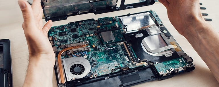
Fact 4: Printed Circuit Boards (PCBs)
Most electronic appliances require complex electronic circuits. That’s why designers have to arrange tiny electronic components on a circuit board. It comprises a plastic board with connecting copper tracks on one side and lots of holes to affix the components. When the layout of a circuit board is printed chemically onto a plastic board, it is called a printed circuit board or PCB.
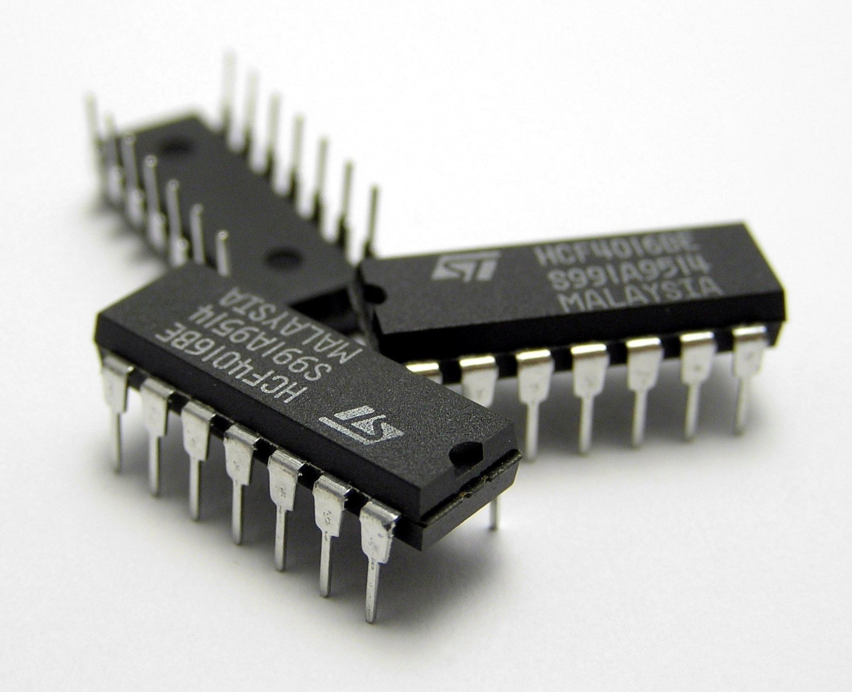
Fact 5: Integrated Circuits (ICs)
Though PCBs can offer a lot of advantages, most modern instruments such as computers and mobiles require complex circuits, having thousands and even millions of components. That’s where integrated circuits come in. They are the tiny electronic circuits that can fit inside a small silicon chip. Jack Kilby invented the first integrated circuit in 1958 at Texas Instruments. The sole purpose of ICs is to increase the efficiency of the electronic devices, while reducing their size and manufacturing cost. Over the years, integrated circuits have become increasingly sophisticated as technology continues to evolve. That’s why personal computers, laptops, mobiles phones, and other consumer electronics are getting cheaper and better by the day.
Electronic Components
Thanks to modern technology, electronic circuit building process has been completely automated, especially for building ICs and PCBs. The number and arrangement of components in a circuit may vary depending on its complexity. However, it is built using a small number of standard components.
The following components are used to construct electronic circuits.
Component 1: Capacitor
Capacitors are widely used to build different types of electronic circuits. A capacitor is a passive two-terminal electrical component that can store energy in an electric field electrostatically. In simple terms, it works as a small rechargeable battery that stores electricity. However, unlike a battery, it can charge and discharge in the split of a second.
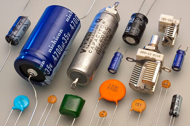
A. Composition
Capacitors come in all shapes and sizes, but they usually have the same primary components. There are two electrical conductors or plates separated by a dielectric or insulator stacked between them. Plates are composed of conducting material such as thin films of metal or aluminum foil. A dielectric, on the other hand, is a non-conducting material such as glass, ceramic, plastic film, air, paper, or mica. You can insert the two electrical connections protruding from the plates to fix the capacitor in a circuit.
B. How Does It Work?
When you apply a voltage over the two plates or connect them to a source, an electric field develops across the insulator, causing one plate to accumulate positive charge while negative charge gets collected on the other. The capacitor continues to hold its charge even if you disconnect it from the source. The moment you connect it to a load, the stored energy will flow from the capacitor to the load.
Capacitance is the amount of energy stored in a capacitor. The higher the capacitance, the more energy it can store. You can increase the capacitance by moving the plates closer to each other or increasing their size. Alternatively, you can also enhance the insulation qualities to increase the capacitance.
C. Function and Significance
Though capacitors look like batteries, they can perform different types of functions in a circuit such as blocking direct current while allowing alternating current to pass or smooth the output from a power supply. They are also used in electric power transmission systems to stabilize voltage and power flow. One of the most significant functions of a capacitor in the AC systems is power factor correction, without which you can’t provide sufficient amount of starting torque to single phase motors.
Filters Capacitor Applications
If you are using a microcontroller in a circuit to run a specific program, you don’t want its voltage to drop as that will reset the controller. That’s why designers use a capacitor. It can supply the microcontroller with the necessary power for a split second to avoid a restart. In other words, it filters out the noise on the power line and stabilizes the power supply.
Hold-Up Capacitor Applications
Unlike a battery, a capacitor releases its charge rapidly. That’s why it is used to provide power to a circuit for a short while. Your camera batteries charge the capacitor attached to the flash gun. When you take a flash photograph, the capacitor releases its charge in a split second to generate a flash of light.
Timer Capacitor Applications
In a resonant or time-dependent circuit, capacitors are used along with a resistor or inductor as a timing element. The time required to charge and discharge a capacitor determines the operation of the circuit.
Component 2: Resistor
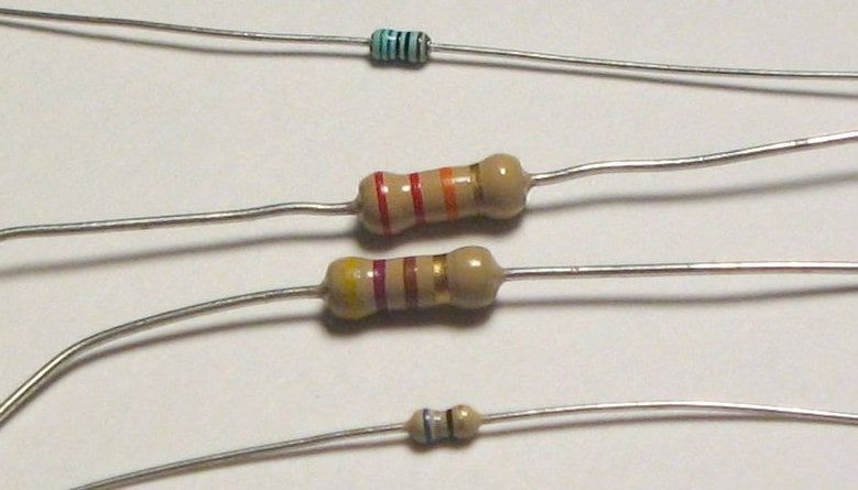
A resistor is a passive two-terminal electrical device that resists the flow of current. It is probably the simplest element in an electronic circuit. It is also one of the most common components as resistance is an inherent element of nearly all electronic circuits. They are usually color-coded.
A. Composition
A resistor is not a fancy device at all because resistance is a natural property possessed by almost all conductors. So, a capacitor consists of a copper wire wrapped around an insulating material such as a ceramic rod. The number of turns and the thinness of copper wire are directly proportional to the resistance. The higher the number of turns and thinner the wire, the higher the resistance.
You can also find resistors made of a spiral pattern of a carbon film. Hence, the name carbon film resistors. They are designed for lower-power circuits because carbon film resistors are not as precise as their wire-wound counterparts. However, they are cheaper than wired resistors. Wire terminals are attached to the both ends. As resistors are blind to the polarity in a circuit, the current can flow through in either direction. So, there is no need to worry about attaching them in a forward or a backward direction.
B. How Does It Work?
A resistor may not look like much. One may think it doesn’t do anything except consume power. However, it performs a vital function: controlling the voltage and the current in your circuit. In other words, resistors give you control over the design of your circuit.
When electric current starts flowing through a wire, all the electrons start moving in the same direction. It’s just like water flowing through a pipe. Less amount of water will flow through a thin pipe because there is less room for its movement.
Similarly, when the current passes through a thin wire in a resistor, it becomes progressively harder for the electrons to wiggle through it. In short, the number of electrons flowing through a resistor goes down as the length and thinness of the wire increases.
C. Function and Significance
Resistors have plenty of applications, but the three most common ones are managing current flow, dividing voltage, and resistor-capacitor networks.
Limiting the Flow of Current
If you don’t add resistors to a circuit, the current will flow at dangerously high levels. It can overheat other components and possibly damage them. For example, if you connect an LED directly to a battery, it would still work. However, after some time the LED will heat up like a fireball. It will eventually burn as LEDs are less tolerant to heat.
But, if you introduce a resistor in the circuit, it will reduce the flow of current to an optimal level. Thus, you can keep the LED on longer without overheating it.
Dividing Voltage
Resistors are also used to reduce the voltage to the desired level. Sometimes, a particular part of a circuit such as a microcontroller may need a lower voltage than the circuit itself. This is where a resistor comes in.
Let’s say your circuit runs off of a 12V battery. However, the microcontroller needs only a 6V supply. So, to divide the voltage in half, all you have to do is place two resistors of equal resistance value in series. The wire in between the two resistors will have halved the voltage of your circuit where the microcontroller can be attached. Using appropriate resistors, you can lower the voltage within the circuit to any level.
Resistor-Capacitor Networks
Resistors are also used in combination with capacitors to build ICs that contain resistor-capacitor arrays in a single chip. They are also known as RC filters or RC networks. They are often used to suppress electromagnetic Interference (EMI) or Radio Frequency Interference (RFI) in various instruments, including input/output ports of computers and laptops, Local Area Networks (LANs), and Wide Area Networks (WANs), among others. They are also used in machine tools, switchgears, motor controllers, automated equipment, industrial appliances, elevators, and escalators.
Component 3: Diode
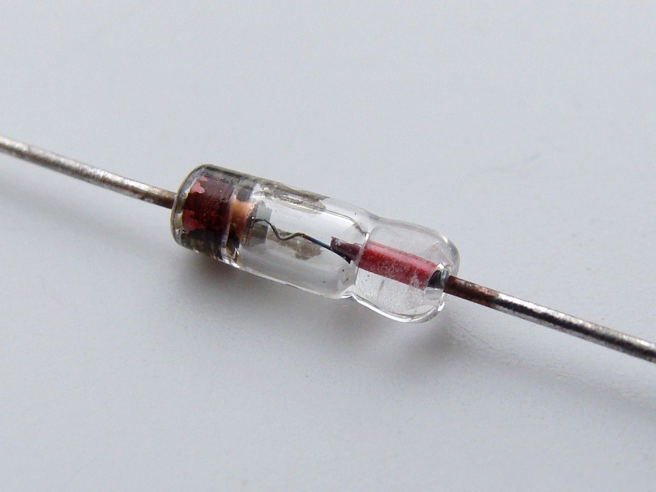
A diode is a two-terminal device that allows electric current to flow in only one direction. Thus, it is the electronic equivalent of a check valve or a one-way street. It is commonly used to convert an Alternating Current (AC) into a Direct Current (DC). It is made either of a semiconductor material (semiconductor diode) or vacuum tube (vacuum tube diode). Today, however, most diodes are made from semiconductor material, particularly silicon.
A. Composition
As mentioned earlier, there are two types of diodes: vacuum diodes and semiconductor diodes. A vacuum diode consists of two electrodes (cathode and anode) placed inside a sealed vacuum glass tube. A semiconductor diode comprises p-type and n-type semiconductors. It is, therefore, known as a p-n junction diode. It is usually made of silicon, but you can also use germanium or selenium.
B. How Does It Work?
Vacuum Diode
When the cathode is heated by a filament, an invisible cloud of electrons, called space charge, forms in the vacuum. Though electrons are emitted from the cathode, the negative space charge repels them. As electrons can’t reach the anode, no current flows through the circuit. However, when the anode is made positive, the space charge vanishes. As a result, current starts flowing from the cathode to the anode. Thus, electric current within the diode flows only from the cathode to the anode and never from the anode to the cathode.
P-N Junction Diode
A p-n junction diode comprises p-type and n-type semiconductors of silicon. The p-type semiconductor is usually doped with boron, leaving holes (positive charge) in it. The n-type semiconductor, on the other hand, is doped with antimony, adding a few extra electrons (negative charge) in it. So, electric current can flow through both semiconductors.
When you put p-type and n-type blocks together, the extra electrons from the n-type combine with the holes in the p-type, creating a depletion zone without any free electrons or holes. In short, current can no longer pass through the diode.
When you connect the battery’s negative terminal to the n-type silicon and the positive terminal to p-type (forward-bias), current starts to flow as electrons and holes can now move across the junction. However, if you reverse the terminals (reverse-bias), no current flows through the diode because holes and electrons are pushed away from each other, widening the depletion zone. So, just like a vacuum diode, a junction diode can also allow current to pass in one direction only.
C. Function and Significance
Though diodes are one of the simplest components in an electronic circuit, they have unique applications across industries.
AC to DC Conversion
The most common and important application of a diode is the rectification of AC power to DC power. Usually, a half-wave (single diode) or a full-wave (four diodes) rectifier is used to convert AC power into DC power, particularly in household power supply. When you pass AC power supply through a diode, only half the AC waveform passes through it. As this voltage pulse is used to charge the capacitor, it produces steady and continuous DC currents without any ripples. Different combinations of diodes and capacitors are also used to build various types of voltage multipliers to multiply a small AC voltage into high DC outputs.
Bypass Diodes
Bypass diodes are often used to protect solar panels. When the current from the rest of the cells passes through a damaged or dusty solar cell, it causes overheating. As a result, the overall output power decreases, creating hot spots. The diodes are connected parallel to the solar cells to protect them against this overheating problem. This simple arrangement limits the voltage across the bad solar cell while allowing the current to pass through undamaged cells to the external circuit.
Voltage Spike Protection
When the power supply is suddenly interrupted, it produces a high voltage in most inductive loads. This unexpected voltage spike can damage the loads. However, you can protect expensive equipment by connecting a diode across the inductive loads. Depending on the type of security, these diodes are known by many names including snubber diode, flyback diode, suppression diode, and freewheeling diode, among others.
Signal Demodulation
They are also used in the process of signal modulation because diodes can remove the negative element of an AC signal efficiently. The diode rectifies the carrier wave, turning it into DC. The audio signal is retrieved from the carrier wave, a process called audio-frequency modulation. You can hear the audio after some filtering and amplification. Hence, diodes are commonly found in radios to extract the signal from the carrier wave.
Reverse Current Protection
Reversing polarities of a DC supply or incorrectly connecting the battery can cause a substantial current to flow through a circuit. Such a reverse connection can damage the connected load. That’s why a protective diode is connected in series with the positive side of the battery terminal. The diode becomes forward-biased in the case of correct polarity and the current flows through the circuit. However, in the event of a wrong connection, it becomes reverse-biased, blocking the current. Thus, it can protect your equipment from potential damage.
Component 4: Transistor
One of the most crucial components of an electronic circuit, transistors have revolutionized the field of electronics. These tiny semiconductor devices with three terminals have been around for more than five decades now. They are often used as amplifiers and switching devices. You can think of them as relays without any moving parts because they can turn something ‘on’ or ‘off’ without any movement.
A. Composition
In the beginning, Germanium was used to build transistors which were extremely temperature-sensitive. Today, however, they are made from Silicon, a semiconductor material found in the sand because Silicon transistors are much more temperature-tolerant and cheaper to manufacture. There are two different types of Bipolar Junction Transistors (BJT), NPN and PNP. Each transistor has three pins called Base (b), collector (c), and emitter (e). NPN and PNP refer to the layers of semiconductor material used to make the transistor.
B. How Does It Work?
When you sandwich a p-type silicon slab between two n-type bars, you get an NPN transistor. The emitter is attached to one n-type, while the collector is attached to the other. The base is attached to the p-type. The surplus holes in the p-type silicon act as barriers, blocking the flow of the current. However, if you apply a positive voltage to the base and the collector and negatively charge the emitter, electrons start flowing from the emitter to the collector.
The arrangement and number of p-type and n-type blocks remain inverted in a PNP transistor. In this type of transistor, one n-type is sandwiched between two p-type blocks. As voltage allocation is different, a PNP transistor works differently. An NPN transistor requires a positive voltage to the base, while a PNP requires a negative voltage. In short, the current must flow away from the base to turn a PNP transistor on.
C. Function and Significance
Transistors function as both, switches and amplifiers in most electronic circuits. Designers often use a transistor as a switch because unlike a simple switch, it can turn a small current into a much larger one. Though you can use a simple switch in an ordinary circuit, an advanced circuit may need varying amounts of currents at different stages.
Transistors in Hearing Aids
One of the most well-known applications of transistors is the hearing aid. Usually, a small microphone in the hearing aid picks up the sound waves, converting them into fluctuating electrical pulses or currents. When these currents pass through a transistor, they are amplified. The amplified pulses then pass through a speaker, converting them into sound waves once again. Thus, you can hear a substantially louder version of the surrounding noise.
Transistors in Computers and Calculators
We all know that computers store and process information using the binary language of “zero” and “one.” However, most people don’t know that transistors play a critical role in making something called logic gates, which are the backbones of computer programs. Transistors are often hooked up with logic gates to build a unique piece of an arrangement called a flip-flop. In this system, the transistor remains ‘on’ even if you remove the base current. It now flips on or off whenever new current passes through it. Thus, a transistor can store a zero when it’s off or a one when it’s on, which is the working principle of computers.
Darlington Transistors
A Darlington transistor is made of two PNP or NPN polar junction transistors placed together. It is named after its inventor Sidney Darlington. The sole purpose of a Darlington transistor is to deliver a high current gain from a low base current. You can find these transistors in instruments that require a high current gain at a low frequency such as power regulators, display drivers, motor controllers, light and touch sensors, alarm systems, and audio amplifiers.
IGBT and MOSFET Transistors
The Insulated-Gate Bipolar Transistor (IGBT) transistors are often used as amplifiers and switches in various instruments including electric cars, trains, refrigerators, air-conditioners, and even stereo systems. On the other hand, Metal-Oxide-Semiconductor Field-Effect Transistors (MOSFET) are commonly used in integrated circuits to control a device’s power levels or for storing data.
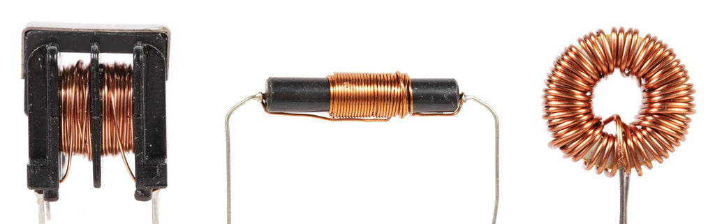
Component 5: Inductor
An inductor, also known as a reactor, is a passive component of a circuit having two terminals. This device stores energy in its magnetic field, returning it to the circuit whenever required. It was discovered that when two inductors are placed side by side without touching, the magnetic field created by the first inductor affects the second inductor. It was a crucial breakthrough that led to the invention of the first transformers.
A. Composition
It is probably the simplest component, comprising just a coil of copper wire. The inductance is directly proportional to the number of turns in the coil. Sometimes, however, the coil is wound around a ferromagnetic material such as iron, laminated iron, and powdered iron to increase the inductance. The shape of this core can also increase the inductance. Toroidal (donut-shaped) cores provide better inductance compared to solenoidal (rod-shaped) cores for the same number of turns. Unfortunately, it is difficult to join inductors in an integrated circuit, so they are usually replaced by resistors.
B. How Does It Work?
Whenever the current passes through a wire, it creates a magnetic field. However, the unique shape of the inductor leads to the creation of a much stronger magnetic field. This powerful magnetic field, in turn, resists alternating current, but it lets direct current flow through it. This magnetic field also stores energy.
Take a simple circuit comprising a battery, a switch, and a bulb. The bulb will glow brightly the moment you turn the switch on. Add an inductor to this circuit. As soon you turn the switch on, the bulb changes from bright to dim. On the other hand, when the switch is turned off, it becomes very bright, just for a fraction of a second before turning off completely.
As you turn the switch on, the inductor starts using the electricity to create a magnetic field, temporarily blocking the current flow. But, only DC current passes through the inductor as soon as the magnetic field is complete. That’s why the bulb changes from bright to dim. All this time, the inductor stores some electrical energy in the form of magnetic field. So, when you turn the switch off, the magnetic field keeps the current in the coil steady. Thus, the bulb burns brightly for a while before turning off.
C. Function and Significance
Though inductors are useful, it is difficult to incorporate them into electronic circuits due to their size. As they are bulkier compared to other components, they add a lot of weight and occupy plenty of space. Hence they are usually replaced by resistors in integrated circuits (ICs). Still, inductors have a wide range of industrial applications.
Filters in Tuned Circuits
One of the most common applications of inductors is to select the desired frequency in tuned circuits. They are used extensively with capacitors and resistors, either in parallel or series, to create filters. The impedance of an inductor increases as the frequency of signal increases. Thus, a stand-alone inductor can only act as a low-pass filter. However, when you combine it with a capacitor, you can create a notched filter because the impedance of a capacitor decreases as the frequency of signal increase. So, you can use different combinations of capacitors, inductors, and resistors to create various types of filters. They are found in most electronics including televisions, desktop computers, and radios.
Inductors as Chokes
If an alternate current flows through an inductor, it creates an opposite current flow. Thus, it can convert an AC supply into a DC. In other words, it chokes the AC supply but allows the DC to pass through it, hence the name ‘choke.’ Usually, they are found in power supply circuits that need to convert AC supply to DC supply.
Ferrite Beads
A ferrite bead or ferrite choke is used to suppress high-frequency noise in electronic circuits. Some of the common uses of ferrite beads include computer cables, television cables, and mobile charge cables. These cables can, sometimes, act as antennas, interloping with audio and video output of your television and computer. So, inductors are used in ferrite beads to reduce such radio frequency interference.
Inductors in Proximity Sensors
Most proximity sensors work on the principle of inductance. An inductive proximity sensor comprises four parts including an inductor or coil, an oscillator, a detection circuit and an output circuit. The oscillator generates a fluctuating magnetic field. Whenever an object comes into the proximity of this magnetic field, eddy currents start to build up, reducing the sensor’s magnetic field.
The detection circuit determines the strength of the sensor, while output circuit triggers the appropriate response. Inductive proximity sensors, also called contactless sensors, are cherished for their reliability. They are used at traffic lights to detect the traffic density and also as parking sensors in cars and trucks.
Induction Motors
An induction motor is probably the most common example of the application of inductors. Usually, in an induction motor, inductors are placed in a fixed position. In other words, they are not allowed to align with the nearby magnetic field. An AC power supply is used to create a rotating magnetic field which then rotates the shaft. The power input controls the speed of rotation. Hence, inductions motors are often used in fixed speed applications. The induction motors are very reliable and robust because there is no direct contact between the motor and the rotor.
Transformers
As mentioned earlier, the discovery of inductors led to the invention of transformers, one of the fundamental components of power transmission systems. You can create a transformer by combining the inductors of a shared magnetic field. They are usually used to increase or decrease voltages of the power lines to the desired level.
Energy Storage
Just like a capacitor, an inductor can also store energy. However, unlike a capacitor, it can store energy for a limited time. As the energy is stored in a magnetic field, it collapses as soon as the power supply is removed. Still, inductors function as reliable energy storage device in switch mode power supply such as desktop computers.
Component 6: Relay
A relay is an electromagnetic switch that can open and close circuits electromechanically or electronically. You need a relatively small current to operate a relay. Usually, they are used to regulate low currents in a control circuit. However, you can also use relays to control high electric currents. A relay is the electrical equivalent of a lever. You can switch it on with a small current to turn on (or leverage) another circuit using large current. Relays are either electromechanical relays or solid-state relays.
A. Composition
An Electromechanical Relay (EMR) comprises a frame, coil, armature, spring, and contacts. The frame supports various parts of the relay. The armature is the moving part of a relay switch. A coil (mostly copper wire), wound around a metal rod generates a magnetic field that moves the armature. Contacts are the conducting parts that open and close the circuit.
A Solid-State Relay (SSR) consists of an input circuit, a control circuit, and an output circuit. The input circuit is the equivalent of a coil in an electromechanical relay. The control circuit acts as a coupling device between input and output circuits, while the output circuit performs the same function as the contacts in an EMR. Solid-state relays are becoming increasingly popular as they are cheaper, faster, and reliable compared to electromechanical relays.
B. How Does It Work?
Whether you are using an electromechanical relay or a solid-state relay, it is either a Normally Closed (NC) or a Normally Opened (NO) relay. In case of an NC relay, the contacts remain closed when there is no power supply. However, in a NO relay, the contacts remain open when there is no power supply. In short, whenever current flows through a relay, the contacts will either open or close shut.
In an EMR, power supply energizes the relay coil, creating a magnetic field. The magnetic coil attracts a ferrous plate mounted on the armature. When the current stops, the armature is released into its resting position by spring action. An EMR can also have single or multiple contacts within a single package. If a circuit uses only one contact, it is called a Single Break (SB) circuit. A Double Break Circuit (DB), on the other hand, comes with tow contacts. Usually, single break relays are used to control low power devices such as indicator lamps, while double break contacts are used to regulate high-power devices such as solenoids.
When it comes to operating an SSR, you need to apply a voltage higher than the specified pickup voltage of the relay to activate the input circuit. You have to apply a voltage less than the stipulated minimum dropout voltage of the relay to deactivate the input circuit. Control circuit transfers the signal from the input circuit to the output circuit. The output circuit switches on the load or performs the desired action.
C. Function and Significance
As they can control a high current circuit by a low current signal, most control processes use relays as the primary protection and switching devices. They can also detect fault and irregularities occurring in the power distribution systems. Typical applications include telecommunication, automobiles, traffic control systems, home appliances, and computers among others.
Protective Relays
Protective relays are used to trip or isolate a circuit if any irregularities are detected. Sometimes, they can also set off alarms when a fault is detected. Types of protection relays depend on their function. For example, an overcurrent relay is designed to identify the current exceeding a predetermined value. When such current is detected, the relay operates tripping a circuit breaker to protect the equipment from potential damage.
A distance relay or impedance relay, on the other hand, can detect abnormalities in the ratio of current and voltage rather than monitoring their magnitude independently. It swarms into action when the V/I ratio falls below a predetermined value. Usually, protective relays are used to protect equipment such as motors, generators, and transformers, and so on.
Automatic Reclosing Relay
An automatic reclosing relay is designed to cause multiple reclosures of a circuit breaker that is already tripped by a protective relaying. For example, when there is a sudden voltage drop, the electrical circuit in your home may experience several brief power outages. These outages occur because a reclosing relay is trying to switch on the protective relay automatically. If it succeeds the power supply will be restored. If not, there will be a complete blackout.
Thermal Relays
The thermal effect of electrical energy is the working principle of a thermal relay. In short, it can detect the rise the ambient temperature and switch on or off a circuit accordingly. It consists of a bimetallic strip which heats up if an overcurrent passes through it. The heated strip bends and closes the No contact, tripping the circuit breaker. The most common application of thermal relay is overload protection of electric motor.
Component 7. Quartz Crystal
Quartz crystals have several applications in the electronics industry. However, they are mostly used as resonators in electronic circuits. Quartz is a naturally occurring form of silicon. However, it is now produced synthetically to meet the growing demand. It exhibits the piezoelectric effect. If you apply physical pressure on one side, the resulting vibrations generate an AC voltage across the crystal. Quartz crystal resonators are available in many sizes according to the required applications.
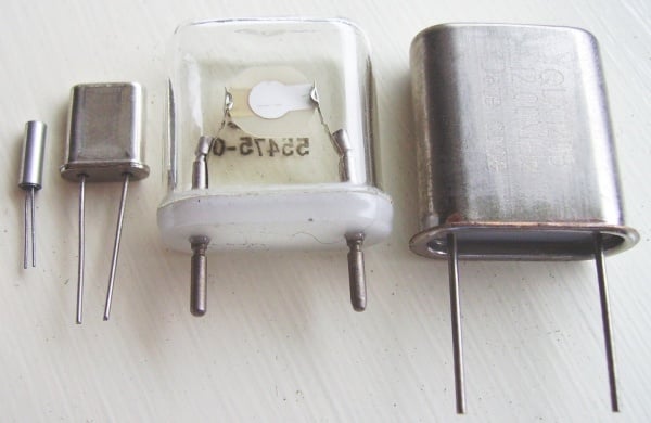
A. Composition
As mentioned earlier, quartz crystals are either synthetically manufactured or occur naturally. They are often used to make crystal oscillators to create an electrical signal with a precise frequency. Usually, the shape of quartz crystals is hexagonal with pyramids at ends. However, for practical purposes, they are cut into rectangular slabs. The most common types of cutting formats include X cut, Y cut, and AT cut. This slab is placed between two metal plates called holding plates. The outer shape of a quartz crystal or crystal oscillator can be cylindrical, rectangular or square.
B. How Does It Work?
If you apply an alternating voltage to a crystal, it causes mechanical vibrations. The cut and the size of the quartz crystal determine the resonant frequency of these vibrations or oscillations. Thus, it generates a constant signal. Quartz oscillators are cheap and easy to manufacture synthetically. They are available in the range from a few KHz to a few MHz. As they have a higher quality factor or Q factor, crystal oscillators are remarkably stable with respect to time and temperature.
C. Function and Significance
The exceptionally high Q factor enables you to use quartz crystals and the resonant element in oscillators as well as filters in electronic circuits. You can find this highly reliable component in radio frequency applications, as oscillator clock circuits in microprocessor boards, and as a timing element in digital watches as well.
Quartz Watches
The problem with traditional coil spring watches is that you have to keep winding the coil periodically. Pendulum watches, on the other hand, depend on the force of gravity. Thus, they tell time differently at different sea levels and altitudes due to changes in the gravitational force. The performance of quartz watches, however, is not affected by any of these factors. Quartz watches are battery-powered. Usually, a tiny crystal of quartz regulates the gears that control the second, the minute, and the hour hands. As quartz watches use very little energy, the battery can often last longer.
Filters
You can also use quartz crystals in an electronic circuit as filters. They are often used to filter out unwanted signals in radios and microcontrollers. Most basic filters consist of a single quartz crystal. However, advanced filters may comprise more than one crystal to match the performance requirements. These quartz crystal filters are far superior to the ones manufactured using LC components.
Conclusion
From communicating with your loved ones living across continents to making a hot cup of coffee, electronic gadgets touch almost every aspect of our lives. However, what makes these electronic gadgets finish seemingly time-consuming tasks in just a few minutes? Tiny electronic circuits are the foundation of all electronic equipment. Reading about the various components of an electronic circuit will help you understand their function and significance. Do share your suggestions and views about this in the comments section below.
// This article was published originally on ICRFQ.